Saturday, 2 June 2012

Brake Lines

I. The Update:

Good news! I've finished my studies and now I can continue working on this project. At the moment I'm at the point when all the major components of the car are finished. Now it's all about details. Details are important!

II. The Changelog: 

  • The covers that cover sides of the frame are now riveted
  • All of the sharp edges (bellow 2mm radius) are covered in rubber lining
  • Headlight conduits added
  • Copper brake lines added
  • Flexible brake lines added. (I had to cheat and assemble multiple parts of the flexible line for them to be flexible and not constraint the movement of the suspension)
  • Zip-ties for flexible lines added
  • Frame is now finished. Engine mounts are still missing.
Next on to-do list:
  • Brake fluid reservoir
  • Clutch line
  • WIRING! Not excited about this one..
III. The Images:

A snapshot of the viewport. Shows the true power of Autodesk Inventor

Brake Lines

Headlight conduits
Current state of the car (Rear)


Current state of the car (Front)

Saturday, 25 February 2012

In the previous post I briefly mentioned that I changed the geometry of wishbones and did some redesigning in the suspension bit of the car. Because I had a hectic week, I did not do any actual modelling, so I decided I'd rather explain what has changed.

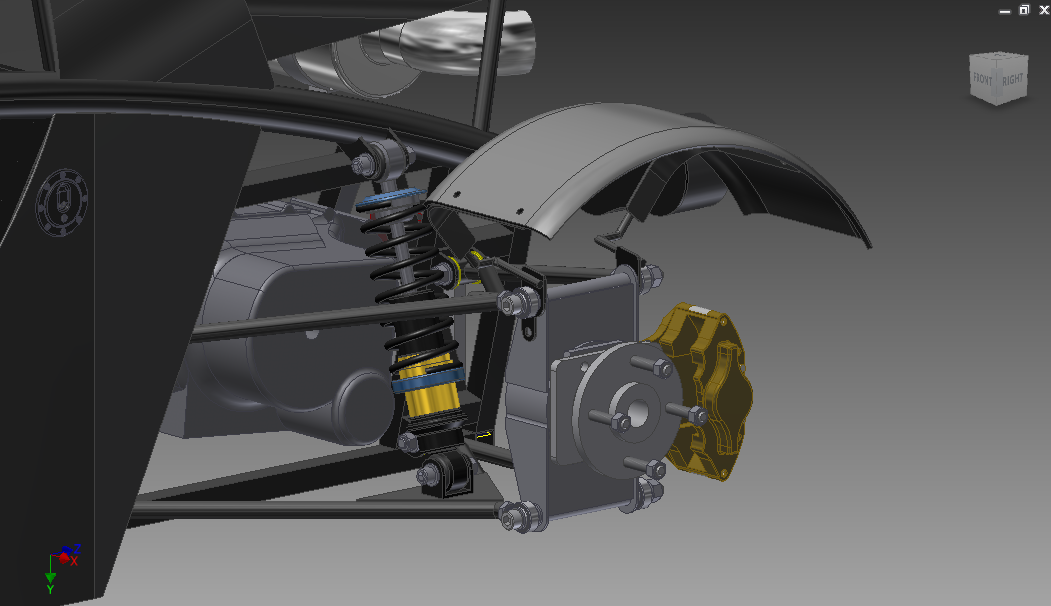
I'll start with a picture of the suspension, so it's easier for me to explain:


As you can see, the upright looks completely different from the one I've started with (on your right). Now because I'll have to actually make the upright myself (do all the cutting, welding, measuring etc.) I took the easy way out. I mirrored the bottom part of the upright to the top, and that got it where it is. Yes, it's heavier. Yes, that means more unsprung weight. But if that is the cost for increasing safety and rigidity, I'm willing to pay the price.

As you can see it's suspended by four rose-joints (rod-ends, u-joints whatever). That might be the problem when I'll need to attach the upright to the wishbones, because It has to be absolutely vertical. Otherwise it may have some camber and toe angle, which for the default setup, is not favourable.

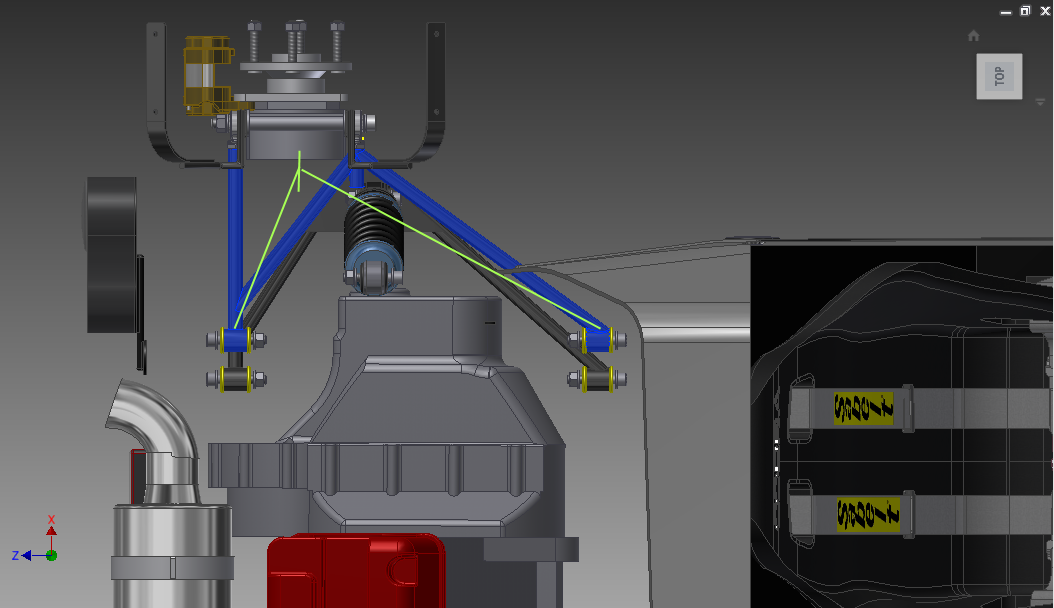
Why did I change the design you ask? Let me try to explain with another picture:


The blue part is the top wishbone. Green lines indicate where the top wishbone used to be in the previous design. Can you see the problem? It hits the damper. That's why I had no other choice than redesign mostly everything. But this is a good thing. The wishbones are now sturdier and can withstand more stress without bending. This design is not the best though. The bushings will wear out faster because of the extreme angle, but that's the price of a wide suspension setup and most of the people can afford it.

Hope this made things a bit more clear.

Saturday, 18 February 2012

I. The Update:

Blog posting schedule change. I'll be posting every Saturday evening, provided that I'll have access to my computer. Now, the kit car bit. As always, not much progress visually, but I have been changing things. You'll see. A lot of things are changing in my life at the moment and I get plenty of tasks from the University. Unfortunately for me and the University, they do not have high priority in my to-do list.

 II. The Changelog:

  • Geometry of the top (bent) support tube (that goes from the front to the rear of the car) changed. Now, instead of two tubes butt-joined together, it's a single tube bent in a single radius, which makes thing a lot simpler and easier to manufacture. But that lead to the next point:
  • Reduced width of the engine bay, which lead to the next point:
  • Longer rear wishbones. I started completely from scratch with this one. Changed the geometry completely. Which, again lead to the next point:
  • Redesigned rear uprights. When the width of the engine bay was reduced, the transmission protruded even further out the frame, therefore the top wishbone would have hit the transmission. So, I needed to widen it a little bit. That wasn't really possible, which meant I had to change the geometry of the upright itself.
  • Redesigned rear cycle wing stays.
  • Headlight conduits.
  • Poly-bushes.
  • A vast amount of nuts, bolts and washers added as well.
  • Mountings for tail-lights.
  • Boosted overall geometry of the frame (diagonal tubes in the rear and the front)
  • Engine cover hinges and supports
  • Front wishbones redesigned from scratch. Some of the dimensions were dodgy, thought I might as well redesign them. No significant geometrical changes.
  • Removed the stripe from the nosecone. (Simplicity is the key)
III. The Images:


Tuesday, 31 January 2012

Let the blogposting continue!


Firstly, some design changes: I tried some colours on the car, and I think white fits it quite well. I'm not saying that I don't like black, it's just that I've spent so much time staring at the black one (while modeling) that I wanted a change. The other obvious thing is the hoop above the roll bar. I didn't particularly like the roll bar sticking out of the car with nothing on it, therefore I figured that the hoop should fix it. The third thing is the engine cover. The old one looked like it was taken from a pick-up truck, that's why it had to be changed.

Now I've also changed the roll bar. Now it should be as rigid as it can be with supports at the right points.


Monday, 12 December 2011

Renderings


A couple of renderings before I leave for Christmas.
I'll be back in February with more processing power and fresh ideas!

Thank You, dear readers.

(Click to open, it's not a small image)


Monday, 5 December 2011

Ford Cortina uprights available for download

Finally!

I'm sharing this Ford Cortina upright. Modelled in Autodesk Inventor by using some drawings that are around the internet and some pictures. Now, the mounting points and the spindle are correct size, should be fine. But the thickness of the upright's plate is not exact. I used pictures and some measuring techniques to get it as close as possible. The angles of the mounting points for the ball joints as well as brake callipers should be correct. (I relied on the drawings mostly)

Use it for whatever you wish. Giving me credit is appreciated.
Have fun.

Download Inventor .ipt file
Download universal CAD .stp file


Sunday, 4 December 2011

Announcement


I'll start uploading some of the models I've created, and start posting short tutorials on how to make things work for you in Inventor. All parts will either be .iam, .ipt or/and .step files.
DISCLAIMER: the models/drawings may not represent the actual looks of the item in real world. When I model something, I try to get the dimensions and the visual appearance as close to the real life item as possible, but some errors still occur. Therefore I ask you not to blame me if you get fired/mess something up in real life if you use my drawings. Use them for concepting purposes, just like I do.

OK, now some updates (pretty pictures only)